📺 详细介绍
探索精彩的游戏世界
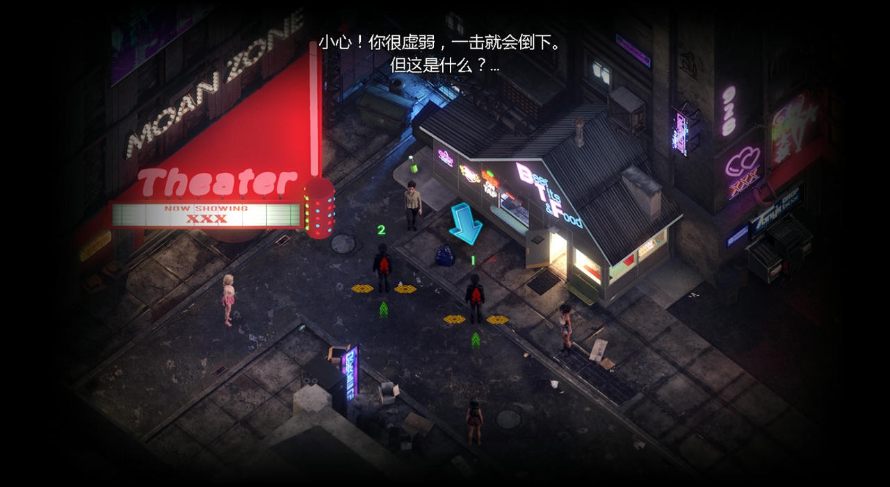
游戏故事
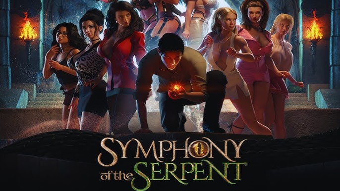
蛇之交响曲是在一个被性病毒吞噬的世界里,一个年轻人发现自己迷失在远离家乡的大城市里,并拥有一件神秘的遗物。
在一群美女的帮助下,发现你的身份,并揭露一个让天堂和地狱陷入战争边缘的复仇阴谋!
🚽 使用攻略
掌握游戏技巧
攻略指南
成为游戏高手的秘诀
新的游戏元素和系统
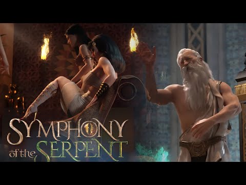
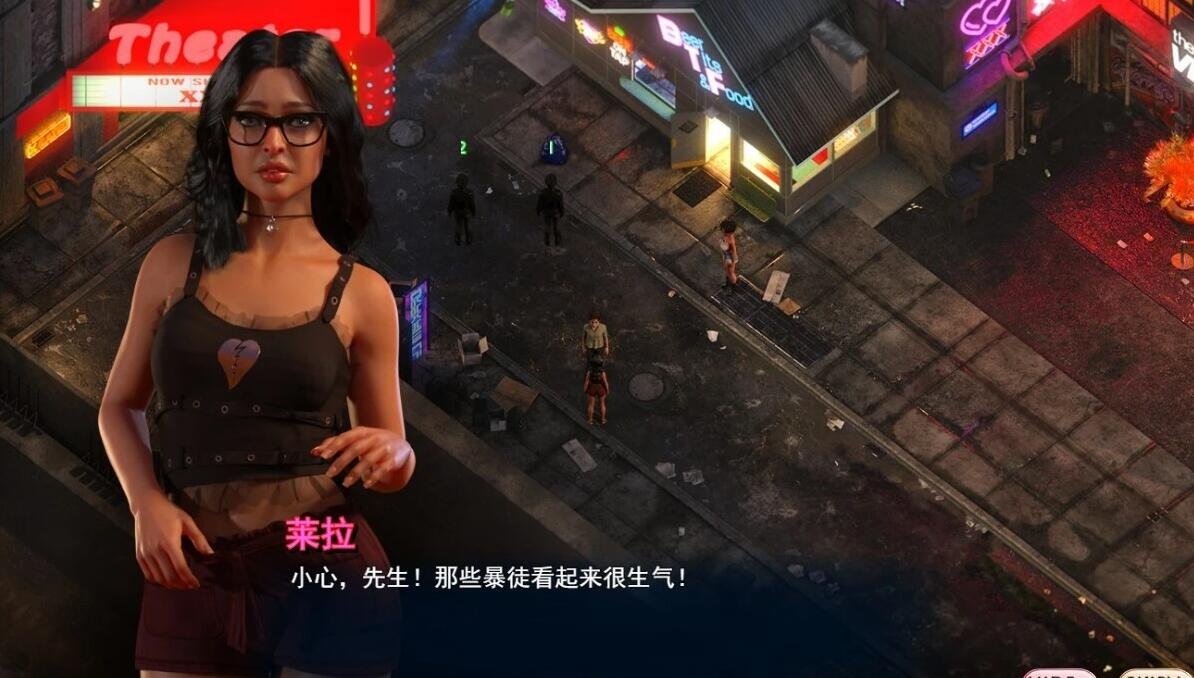
他正在为他的游戏公式带来新的等距视角,与女孩相关的新系统和有趣的机制正在开发中,以便为他的下一个游戏传奇增添更有趣和更奇特的体验。
狂野而神秘的女孩
一群性感而饥渴的女孩将使这些冒险达到新的热度! 如果你能足够好地满足他们…

更新日志】:
游戏作者: NLT Media
蛇之交响曲题外话:
NLT发布了旗下纳迪亚系列的第四部:Symphony of the Serpent蛇之交响曲
前三部分别为:传播欲望、纳迪亚传奇、创世秩序。
大家都知道,我就不吹了,这工作室,东西是做的不错,但是也是一两年一部作品,算是rpg中的佼佼者了。
现在的动画是做的越来越好了,玩了几部,还是被惊艳了一下~
含0419存档
蛇之交响曲个人推荐游玩指数:★★★★【注意事项】
★ 分享的游戏均已测试可正常游玩!
★ 如遇到黑屏/闪退/打不开 请首先检查游戏是否放在非中文路径 如遇乱码请用转区工具右键启动即可游玩
【注意事项】
★ 分享的游戏均已测试可正常游玩!
★ 如遇到黑屏/闪退/打不开 请首先检查游戏是否放在非中文路径 如遇乱码请用转区工具右键启动即可游玩
🗄️ 即刻下载
开始你的冒险之旅
准备好开始游戏了吗?
点击下方按钮,即刻下载完整版游戏,开始你的精彩冒险!
500万+
玩家下载
4.9分
用户评分
100%
安全保障
完全免费,无内购
支持多平台运行
持续更新内容